Properties: adiabatic, not isentropic, symmetric, ![]() inlet based restrictor
inlet based restrictor
Restrictors are discontinuous geometry changes in gas pipes. The loss factor
![]() can be defined based on the inlet conditions or the outlet
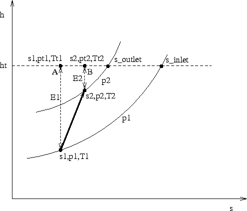
conditions. Focusing on the h-s-diagram (entalpy vs. entropy) Figure (95), the inlet conditions are
denoted by the subscript 1, the outlet conditions by the subscript 2. The
entropy loss from state 1 to state 2 is
can be defined based on the inlet conditions or the outlet
conditions. Focusing on the h-s-diagram (entalpy vs. entropy) Figure (95), the inlet conditions are
denoted by the subscript 1, the outlet conditions by the subscript 2. The
entropy loss from state 1 to state 2 is ![]() . The process is assumed to
be adiabatic, i.e.
. The process is assumed to
be adiabatic, i.e.
![]() , and the same relationship applies to the
total entalpy
, and the same relationship applies to the
total entalpy ![]() , denoted by a dashed line in the Figure.
, denoted by a dashed line in the Figure. ![]() denotes the
kinetic energy part of the entalpy
denotes the
kinetic energy part of the entalpy ![]() , the same applies to
, the same applies to ![]() . Now,
the loss coefficient
. Now,
the loss coefficient ![]() based on the inlet conditions is defined by
based on the inlet conditions is defined by
| (94) |
| (95) |
![]() is the entropy for zero velocity and isobaric conditions at
the inlet, a similar definition applies to
is the entropy for zero velocity and isobaric conditions at
the inlet, a similar definition applies to
![]() . So, for
. So, for
![]() the increase in entropy is compared with the maximum entropy
increase from state 1 at isobaric conditions. Now we have
the increase in entropy is compared with the maximum entropy
increase from state 1 at isobaric conditions. Now we have ![]() and
and
![]() consequently,
consequently,
| (96) |
and based on the outlet conditions by
| (97) |
Using Equation (47) one obtains:
| (98) |
| (99) |
| (100) |
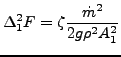
from which [68]
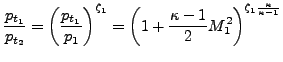 |
(101) |
if ![]() is defined with reference to the first section (e.g. for an
enlargement, a bend or an exit) and
is defined with reference to the first section (e.g. for an
enlargement, a bend or an exit) and
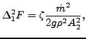
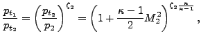 |
(102) |
if ![]() is defined with reference to the second section (e.g. for
a contraction).
is defined with reference to the second section (e.g. for
a contraction).
Using the general gas equation (33) finally leads to (for
![]() ):
):
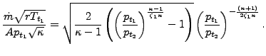 |
(103) |
This equation reaches critical conditions (choking, ![]() ) for
) for
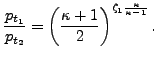 |
(104) |
Similar considerations apply to ![]() .
.
Restrictors can be applied to incompressible fluids as well by specifying the parameter LIQUID on the *FLUID SECTION card. In that case the pressure losses amount to
 |
(105) |
and
 |
(106) |
respectively.
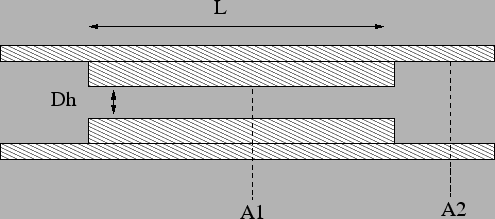
A long orifice is a substantial reduction of the cross section of the pipe over a significant distance (Figure 96).
There are two types: TYPE=RESTRICTOR LONG ORIFICE IDELCHIK with loss coefficients according to [33] and TYPE=RESTRICTOR LONG ORIFICE LICHTAROWICZ with coefficients taken from [43]. In both cases the long orifice is described by the following constants (to be specified in that order on the line beneath the *FLUID SECTION, TYPE=RESTRICTOR LONG ORIFICE IDELCHIK or TYPE=RESTRICTOR LONG ORIFICE LICHTAROWICZ card):
A restrictor of type long orifice MUST be preceded by a restrictor of type
user with ![]() . This accounts for the reduction of cross section from
. This accounts for the reduction of cross section from
![]() to
to ![]() .
.
By specifying the parameter LIQUID on the *FLUID SECTION card the loss is calculated for liquids. In the absence of this parameter, compressible losses are calculated.
Example files: restrictor, restrictor-oil.