The connection of 1D and 2D elements with genuine 3D elements also requires special care and is performed in subroutine ``gen3dconnect.f''. Remember that the expanded elements contain new nodes only, so the connection between these elements and 3D elements, as defined by the user in the input deck, is lost. It must be reinstated by creating multiple point constraints. This, however, does not apply to knots. In a knot, a expandable rigid body is defined with the original node as translational node (recall that a knot is defined by a translational, a rotational and an expansion node). Thus, for a knot the connection with the 3D element is guaranteed. What follows applies to nodes in which no knot was defined.
For 1D beam elements the connection is expressed by the equation (see Figure 159 for the node numbers)
where u stands for any displacement component (or temperature component for heat transfer calculations), i.e. the above equation actually represents 3 equations for mechanical problems, 1 for heat transfer problems and 4 for thermomechanical problems. Notice that only edge nodes of the beam element are used, therefore it can also be applied to midside nodes of beam elements. It expresses that the displacement in the 3D node is the mean of the displacement in the expanded edge nodes.
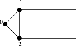
For 2D shell elements the connection is expressed by equation (see Figure 160 for the node numbers)
The same remarks apply as for the beam element.
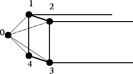
Finally, for plane strain, plane stress and axisymmetric elements the connection is made according to Figure 161 and equation:
Node 1 is the zero-z node of the expanded elements. Although a twenty-node brick element does not use zero-z nodes corresponding the the midside nodes of the original 2D element, they exist and are used in MPC's such as the above equation. The connection is finally established through the combination of the above MPC with the plane strain, plane stress and axisymmetric MPC's linking the zero-z nodes with the negative-z and positive-z nodes.