Previously, a thick cantilever beam was modeled with volume elements. In the present section quadratic beam elements are used for a similar exercise (Section 6.2.33). Beam elements are easy to define: they consist of three nodes on a line. Internally, they are expanded into volumetric elements. There are two types of beam elements: B32 elements, which are expanded into C3D20 elements, and B32R (reduced integration) elements, which are expanded into C3D20R elements. Based on the results in the present section, the B32R element is highly recommended. The B32 element, on the other hand, should be avoided especially if section forces are needed.
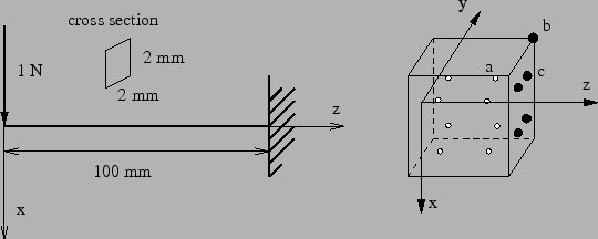
The first cantilever beam which is looked at is 100 mm long and has a square
cross section of 2 x 2
mm![]() . The axis of the beam is along the global
z-direction. This beam is modeled with just one element and loaded at its end
by a unit force in x-direction, Figure 41. We are interested in
the stresses at integration point a and at node b, the section forces at
the beam's fixed end, and the displacement in x at the free end. The location
of the integration point a is at
. The axis of the beam is along the global
z-direction. This beam is modeled with just one element and loaded at its end
by a unit force in x-direction, Figure 41. We are interested in
the stresses at integration point a and at node b, the section forces at
the beam's fixed end, and the displacement in x at the free end. The location
of the integration point a is at
![]() ,
,
![]() and
and
![]() , the nodal coordinates of b are
, the nodal coordinates of b are ![]() ,
, ![]() and
and ![]() [18]. The material is isotropic linear elastic with a Young's modulus of
100,000 MPa and a Poisson's ratio of 0.3.
[18]. The material is isotropic linear elastic with a Young's modulus of
100,000 MPa and a Poisson's ratio of 0.3.
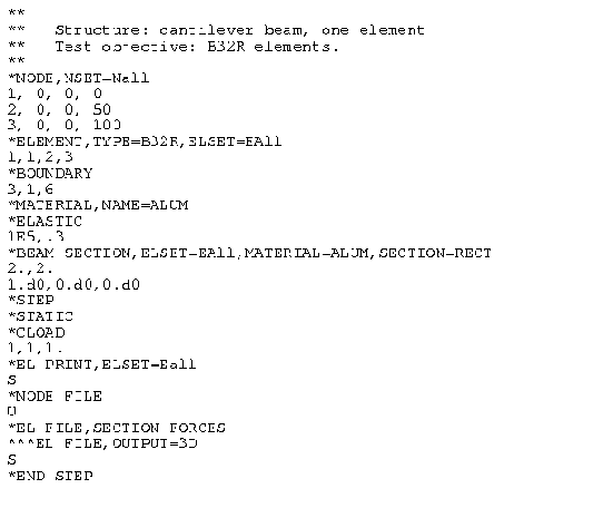
The input deck for this example is very similar to the simplebeam.inp example in the test suite (Figure 42).
The stresses at the integration points are obtained by a *EL PRINT card, the stresses at the nodes by the OUTPUT=3D option (default) on the *EL FILE card, whereas for the section forces the SECTION FORCES option on the same card is used (this option is mutually exclusive with the OUTPUT=3D option). The displacements are best obtained in the non-expanded view, i.e. using the OUTPUT=2D option. This means that for the present results the example had to be run twice: once with the OUTPUT=3D option and once with the SECTION FORCES option.
The results are summarized in Table 3. The
![]() mm
mm![]() N
N![]() s
s![]() K
K![]() system is used. The reference results are analytical
results using simple beam theory [63]. The agreement is
overwhelming. The stresses at the integration points match exactly, so do the
extrapolated normal stresses to the nodes. The shear stresses need special
attention. For a beam the shear stress varies parabolically across the
section. A quadratic volumetric element can simulate only a linear stress
variation across the section. Therefore, the parabolic variation is
approximated by a constant shear stress across the section. Since the
reduced integration points (at
system is used. The reference results are analytical
results using simple beam theory [63]. The agreement is
overwhelming. The stresses at the integration points match exactly, so do the
extrapolated normal stresses to the nodes. The shear stresses need special
attention. For a beam the shear stress varies parabolically across the
section. A quadratic volumetric element can simulate only a linear stress
variation across the section. Therefore, the parabolic variation is
approximated by a constant shear stress across the section. Since the
reduced integration points (at
![]() ) happen to be points at which the parabolic stress
variation attains its mean value the values at the integration points are
exact! The extrapolated values to the nodes take the same constant value and
are naturally wrong since the exact value at the corners is zero.
) happen to be points at which the parabolic stress
variation attains its mean value the values at the integration points are
exact! The extrapolated values to the nodes take the same constant value and
are naturally wrong since the exact value at the corners is zero.
The section forces are obtained by
As shown by Table 3 this procedure yields the correct section forces for the square beam.
The displacements at the beam tip are off by 10 %. The deformation of a beam subject to a shear force at its end is third order, however, the C3D20R element can only simulate a quadratic behavior. The deviation is reduced to 2.4 % by using 5 elements (Table 4). Notice that integration point a is now closer to the fixation (same position is before but in the element adjacent to the fixation).
The same beam was now subjected to a torque of 1 Nmm at its free end. The results are summarized in Table 5.
The torque is matched perfectly, the torsion at the end of the beam (![]() is
the displacement in y-direction at the corresponding node of node b) is off by
15 % [63]. The shear stresses at node b are definitely not correct
(there is no shear stress at a corner node), however, the integration of the
values interpolated from the nodes at the facial integration points yields the
exact torque! Using more elements does not change the values in Table
5.
is
the displacement in y-direction at the corresponding node of node b) is off by
15 % [63]. The shear stresses at node b are definitely not correct
(there is no shear stress at a corner node), however, the integration of the
values interpolated from the nodes at the facial integration points yields the
exact torque! Using more elements does not change the values in Table
5.
The same exercise is now repeated for a circular cross section (radius = 1 mm,
same length, boundary conditions and material data as for the rectangular
cross section). For such a
cross section the vertex nodes of the element lie at
![]() ,
whereas the middle nodes lie at
,
whereas the middle nodes lie at
![]() and
and
![]() . The
integration points are located at
. The
integration points are located at
![]() . The results for bending
with just one element are shown in Table 6 and with 5 elements
in Table 7.
. The results for bending
with just one element are shown in Table 6 and with 5 elements
in Table 7.
For just one element the shear stress is quite close to the analytical value, leading to a even better match of the shear force. This is remarkable an can only be explained by the fact that the cross area of the piecewise quadratic approximation of the circular circumference is smaller and exactly compensates the slightly higher shear stress. A similar effect will be noticed for the torque. The normal stress, however, is far off at the integration points as well as at the nodes leading to a bending moment which is way too small. The same applies to the deformation in x-direction. Using five elements leads to a significant improvement: the bending moment is only 2 % off, the deformation at the free end 9 %. Here again one can argue that the deformation is of cubic order, whereas a quadratic element can only simulate a quadratic change. Using more elements consequently improves the results.
The results for a torque applied to a circular cross section beam is shown in Table 8 (1 element; the results for 5 elements are identical).
Again, it is remarkable that the torque is perfectly matched, although the shear stress at the integration points is 6 % off. This leads to shear values at the vertex nodes which are 19 % off. Interpolation to the facial integration points yields shear stresses of -0.305 MPa. Integration of these stresses finally leads to the perfect torque values. The torsion angle at the end of the beam is 7 %off.
Summarizing, one can state that the use of C3D20R elements leads to quite remarkable results:
It is generally recommended to calculate the stresses from the section forces. The only drawback is the C3D20R element may lead to hourglassing, leading to weird displacements. However, the mean of the displacements across the cross section is usually fine. An additional problem which can arise is that nonlinear geometric calculations may not converge due to this hourglassing. This is remedied in CalculiX by slightly perturbing the coordinates of the expanded nodes (by about 0.1 %).
A similar exercise was performed for the B32 element, however, the results were quite discouraging. The section forces were, especially for bending, way off.