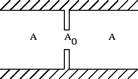
A diaphragm (Figure 118) is characterized by head
losses
![]() of the form:
of the form:
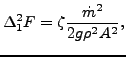 |
(132) |
where ![]() is a head loss coefficient depending on the ratio
is a head loss coefficient depending on the ratio ![]() ,
,
![]() is the mass flow, g is the gravity acceleration and
is the mass flow, g is the gravity acceleration and ![]() is the
liquid density.
is the
liquid density. ![]() and
and ![]() are the cross section of the diaphragm and of
the pipe, respectively. Values for
are the cross section of the diaphragm and of
the pipe, respectively. Values for ![]() can be found in file ``liquidpipe.f''.
can be found in file ``liquidpipe.f''.
The following constants have to be specified on the line beneath the *FLUID SECTION, TYPE=PIPE DIAPHRAGM card:
The gravity acceleration must be specified by a gravity type
*DLOAD card defined for the elements at stake. The material
characteristic ![]() can be defined by a
*DENSITY
card.
can be defined by a
*DENSITY
card.